6 Controller Block Diagram
The block diagram shows the simple function blocks which make up the controller. Where applicable, each block is represented by the ‘P’ code as described in the previous section. The ‘P’ codes set the parameters to match the hardware.
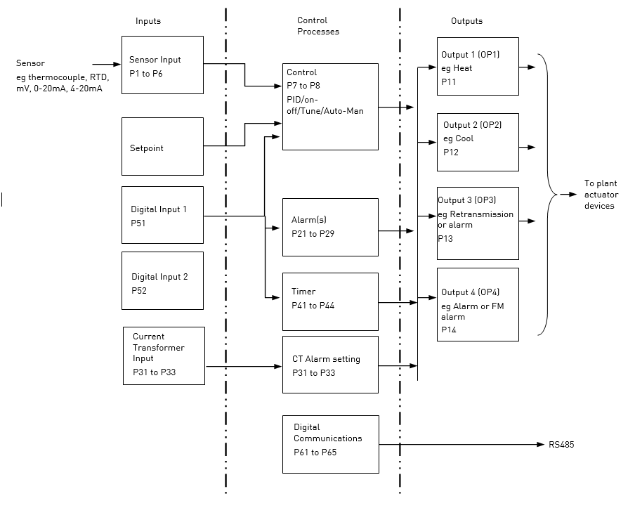
The Temperature (or Process Value, PV) is measured by the sensor and compared with a Setpoint (SP) set by the user.
The purpose of the control block is to reduce the difference between SP and PV (the error signal) to zero by providing a compensating output to the plant via the output driver blocks.
The timer and alarms blocks may be made to operate on a number of parameters within the controller, and digital communications provides an interface for data collection, monitoring and remote control.
The way in which each block performs is defined by its internal parameters. Some of these parameters are available to the user so that they can be adjusted to suit the characteristics of the process which is to be controlled.
These parameters are found in lists in both Operator Level 1 and Operator Level 2 where Level 1 is a sub-set of Level 2.
The above block diagram applies to 808 and 804 controllers.
For 816 Output 3 and Digital Input B are not present.